Newsroom
How to Improve the Installation and Fitting Accuracy of Crossed Roller Bearings
To enhance the actual fitting accuracy during the installation of crossed roller bearings, it is essential to use measurement methods and tools that do not cause deformation to the bearings. Conduct precise actual measurements on the fitting surface dimensions of the bearing's inner bore and outer circle, and measure all relevant items related to the inner and outer diameters. Conduct a comprehensive analysis of the measured data, and based on this, precisely machine the dimensions of the bearing installation parts of the shaft and housing bore. 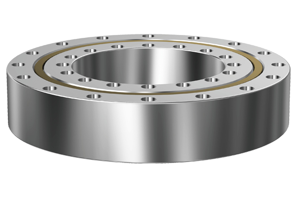
When actually measuring the corresponding dimensions and geometric shapes of the machined shaft and housing bore, the measurements should be carried out under the same temperature conditions as those used for measuring the bearings. To ensure a high actual fitting effect, the surface roughness of the surfaces where the shaft and housing bore match the bearing should be as small as possible. 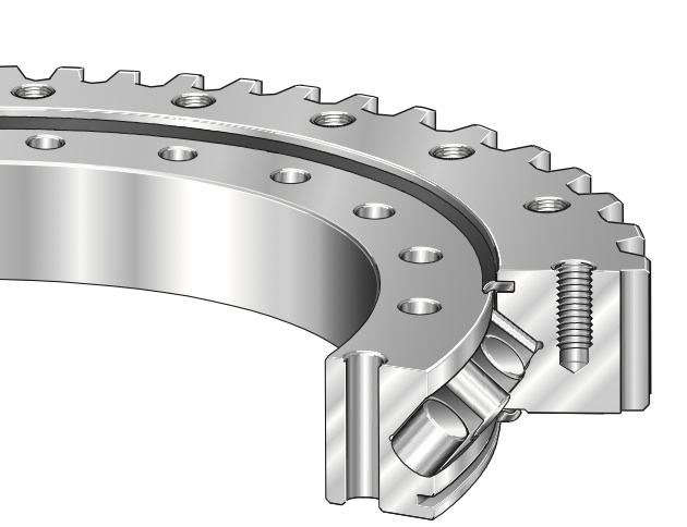
Crossed Cylindrical Roller Bearings
During the aforementioned measurements, two sets of marks indicating the direction of major deviations should be made separately on the outer circle and inner bore of the crossed roller bearing, as well as on the corresponding surfaces of the shaft and housing bore, near both sides of the assembly chamfer. This allows the major deviations of the two matching parts to be aligned in the same direction during actual assembly, so that the deviations of both parts can be partially offset after assembly.
The purpose of making two sets of directional marks is to comprehensively consider the compensation of deviations. This not only improves the rotational accuracy of each bearing at both ends but also partially eliminates the coaxiality error between the housing bore and the shaft journals at both ends of the bearings. 
Implementing surface strengthening measures on the fitting surfaces—such as sandblasting and inserting a precision plug with a slightly larger diameter into the inner bore once—helps improve the fitting accuracy. For large bearings with a large interference fit on the outer ring, to facilitate installation, both the outer circle of the outer ring and the bearing housing bore can be made with a very small taper. During installation, the two tapers are fitted together, and the end cover is used to control the advancement of the outer ring, keeping its interference within a predetermined range. Additionally, the frictional resistance between the end face of the end cover and the end face of the outer ring helps fix the outer ring and prevent it from creeping. This installation method is particularly convenient for vertically installed bearings. 
According to the direction and nature of the load acting on the crossed roller bearing, as well as which side of the inner and outer rings rotates, the load borne by each ring can be classified into rotating load, static load, or non-directional load. The ring bearing rotating load or non-directional load should adopt an interference fit (tight fit). The ring bearing static load can adopt a transition fit or clearance fit (loose fit). When the bearing load is large or the bearing is subject to vibration and impact loads, the interference fit must be increased. When using a hollow shaft, thin-walled bearing housing, or a bearing housing made of light alloy or plastic, the interference fit must also be increased. 
To maintain high rotational speed, high-precision bearings must be used, and the dimensional accuracy of the shaft and bearing housing must be improved to avoid excessive interference. If the interference is too large, the geometric accuracy of the shaft or bearing housing may affect the geometric shape of the bearing ring, thereby impairing the rotational accuracy of the bearing.