Newsroom
Calculate the internal load distribution of the bearing rolling elements
2024-05-15To view the internal load distribution of the bearing rolling elements, please click on the checkbox for 'Rolling Element Load' on the left side of the window, deselect any other checkboxes, and then click the 'Update Report' button to refresh the content.

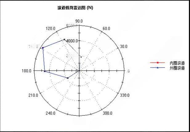
Scroll down the report to view the load distribution chart of the rollers. Display the radial load distribution chart of the bearing rollers. The clockwise direction is positive for angles, and the size of the diameter represents the magnitude of the normal load for each rolling element, measured in Newtons.

From the results, it is evident that not all rollers bear the load. This occurs because this cylindrical roller bearing only withstands radial loads (no axial loads), and the radial load only acts on a few rollers in the load-bearing zone. Among the 11 rollers in this bearing, only 5 rollers bear the load under working conditions. The points representing the remaining 6 rollers are located at the center of the chart, indicating a load of 0.
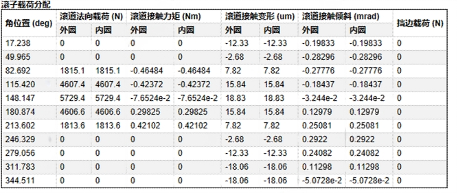
Among the five loaded rollers, the roller at approximately 148 degrees position bears the maximum load, which is 5.7 kN. According to Romax's default rule, this roller is labeled as Roller 1 (refer to the note below).

The load distribution radar chart is suitable for various types of bearing calculations and can clearly display the load-bearing zone, which helps us determine the clearance value and the optimal preload force. The bearing load distribution results are specific to a particular operating condition, corresponding to a single torque value rather than the entire operating range (load spectrum). In this example, 100% load condition is used.
The list below provides the angular position, contact load, torque, deformation, tilt, centrifugal force, and side load for each roller. Only cylindrical roller bearings that bear axial forces have side load results (which are close to 0 in this example).


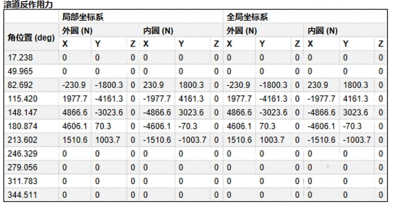
The rolling element loads are expressed in vector form in both the shaft coordinate system and the global coordinate system. If necessary, these values can be applied to an external model to predict housing deformation.
“The numbering principle for the positions of rolling elements in Romax software is as follows:
The roller positioned at the angle where it bears the maximum load is automatically assigned the number 1. Subsequently, the other rolling elements are numbered accordingly. The roller designated as Roller 1 is crucial in determining the bearing life and stress process.”
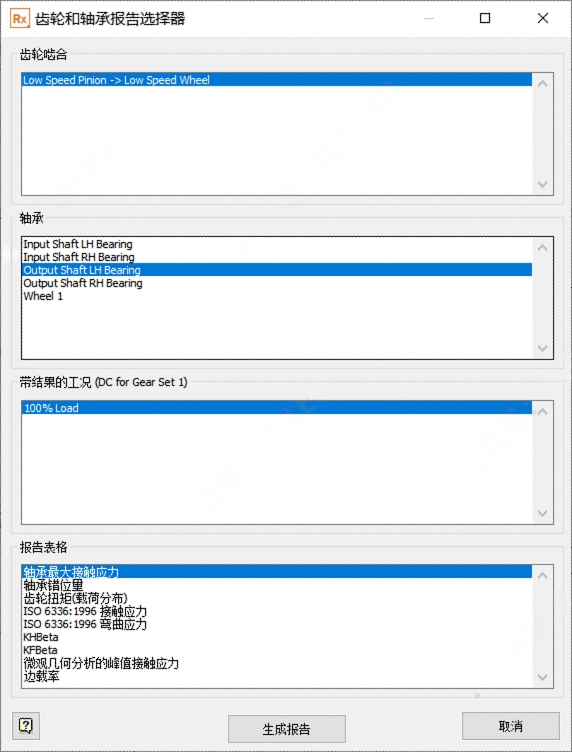
“The Gear and Bearing Report Selector displays selected gear mesh, bearing, and load case results. Here are the steps to view the report:
From the main menu at the top of the software, select "Reports".
Then choose "System Level > Gear and Bearing Report Selector".
Note: Before viewing the results, at least one load case's static analysis must be run.
For gear reports, users must select the correct gear mesh result, while for bearing reports, users must select the correct shaft. Desired reports can be selected in the report table column, then click the "Generate Report" button to open the report.”


