Newsroom
Product Features and Classification of HRB Angular Contact Ball Bearings
Angular contact ball bearings are particularly suitable for withstanding combined loads, i.e., loads acting simultaneously in the radial and axial directions. The axial load-carrying capacity increases with the increase of the contact angle α. The contact angle is defined as follows: the angle between the common normal at the contact point (or midpoint of the contact line) of the rolling element and the raceway, and the radial plane of the bearing is called the bearing contact angle. The load is transmitted from one raceway to the other along this line. For single-row bearings, the size of the contact angle can be identified by different suffixes in the bearing designation. 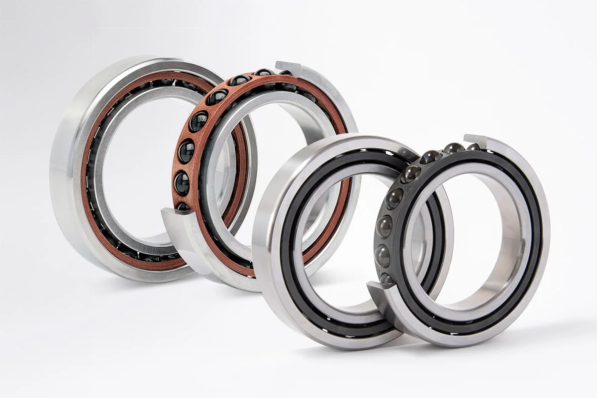
HRB angular contact ball bearings are especially suitable for bearing combined loads (i.e., loads acting simultaneously in the radial and axial directions). Their axial load-carrying capacity increases as the contact angle α becomes larger. The contact angle is defined as: the angle between the common normal at the contact point (or midpoint of the contact line) of the rolling element and the raceway, and the radial plane of the bearing is referred to as the bearing contact angle. The load is transferred from one raceway to the other along this line. For single-row bearings, the magnitude of the contact angle can be recognized by different suffixes in the bearing code.
The angular contact ball bearings produced include:
- Single-row angular contact ball bearings
- Double-row angular contact ball bearings
- Four-point contact ball bearings
Structural Characteristics of Single-Row Angular Contact Ball Bearings
Single-row angular contact ball bearings can only withstand axial loads acting in one direction. When a radial load is applied, an axial force is generated inside the bearing, which requires a counteracting force for adjustment. Therefore, this type of bearing generally needs to be balanced by another bearing. 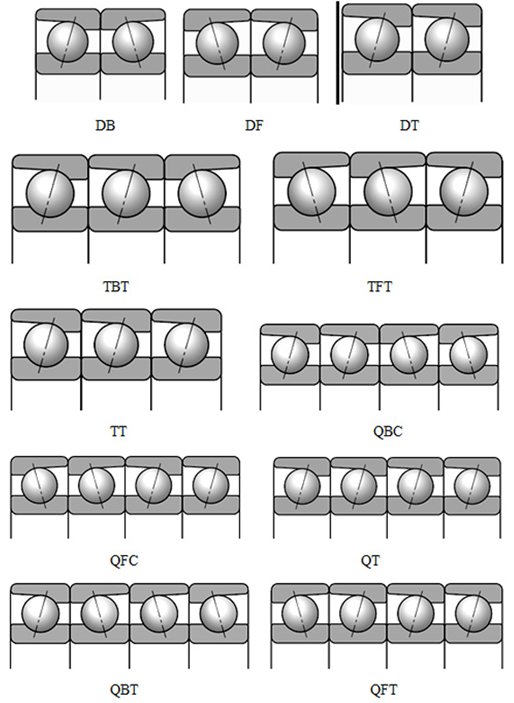
Single-row angular contact ball bearings can be loaded with more steel balls, enabling them to have a higher load-carrying capacity. There are three types of contact angles: 15°, 25°, and 40°, with corresponding suffix designations C, AC, and B respectively. Single-row angular contact ball bearings are divided into two categories: non-separable type and separable type.
Non-separable type bearings: Based on different application scenarios, they are further classified into three series: standard, high-speed, and medium-high-speed.
Separable type bearings: Their inner rings and outer rings can be installed separately, and they are only used in components with limited installation space (such as magnetos). This type of bearing is also known as a magneto bearing.
Retainers for Non-Separable Bearings
The standard structure of non-separable bearings uses an inner ring-guided fiber-reinforced phenolic resin retainer, which is not marked in the bearing designation. When other types of retainers are used, they are indicated by corresponding suffixes:
- TA: Outer ring-guided fiber-reinforced phenolic resin retainer
- TN: Reinforced nylon 66 injection-molded retainer
- M: Brass machined retainer 
Separable Bearings (i.e., Magneto Bearings)
Separable bearings (magneto bearings) mainly use reinforced nylon 66 injection-molded retainers. If required, bearings with brass sheet stamped retainers can also be provided.
Bearings with reinforced nylon 66 injection-molded retainers are suitable for most applications and can work normally within the temperature range of -30°C to 120°C.
Matching and Preload of Single-Row Angular Contact Ball Bearings
Due to the structural characteristics of single-row angular contact ball bearings, they are usually used in a matched configuration of two or more bearings of the same model. The common matching methods are as follows:
1. Back-to-back configuration (DB): Two single-row angular contact ball bearings are mounted back-to-back. The contact angle lines diverge along the axis of rotation. This configuration can well withstand bidirectional axial loads and has high rigidity and anti-overturning moment performance.
2. Face-to-face configuration (DF): Two single-row angular contact ball bearings are mounted face-to-face. The contact angle lines converge toward the axis of rotation. Although its rigidity is relatively low, it can effectively increase the preload.
3. Tandem configuration (DT): Two single-row angular contact ball bearings are mounted in tandem. The contact angle lines are parallel. This configuration can evenly share radial and axial loads but usually only withstands axial loads in one direction. It is often used for opposed installation at both ends of a machine to balance and restrict axial stability. 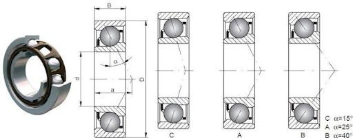
For paired or multi-unit matched bearings, a certain preload must be applied during installation. Selecting an appropriate preload can improve the rigidity of the spindle system, reduce temperature rise, and enhance the machining accuracy of the system. Bearing preloads are divided into three grades: light (A), medium (B), and heavy (C). Users can choose the appropriate grade according to the actual working conditions of the spindle system.
Single-row angular contact ball bearings with a 40° contact angle (suffix B) are manufactured in two types based on different applications:
- One type is suitable for configurations where only one bearing is installed at each bearing position.
- The other type is suitable for configurations where two or more bearings are installed adjacent to each other in any combination (universal matching).
Bearings used for universal matching are specially designed and manufactured to allow adjacent installation in any combination. They can achieve the predetermined axial clearance and uniform load distribution without the need for adjusting shims or similar devices. The suffix indicating universal matching bearings is CB, where "C" stands for clearance and "B" indicates the magnitude of the clearance value. Bearings with smaller or larger clearances are also available (with suffixes CA and CC respectively). For preloaded bearings, light preload, medium preload, and heavy preload are identified by the suffixes GA, GB, and GC respectively (where "G" represents preload or negative clearance).