Newsroom
What are the production process flows of slewing bearings?
Slewing bearings (or slewing rings) are the unsung heroes of heavy machinery, enabling the smooth, controlled rotation of massive structures under immense loads. Found in cranes, excavators, wind turbines, medical scanners, and radar systems, their performance is critical. Manufacturing these precision giants involves a complex, multi-stage production process demanding high levels of engineering expertise, advanced machinery, and rigorous quality control. Here's a detailed look at the typical production workflow of the slewing bearings:
1. Raw Material Selection & Preparation:
Material Choice: The foundation is high-quality, clean alloy steel. Common grades include 42CrMo4, 50Mn, or similar high-carbon chromium steels, often specified by standards like DIN or ASTM. Selection depends on required hardness, toughness, fatigue strength, and corrosion resistance. For highly corrosive environments (offshore wind), stainless steels (e.g., AISI 440C) or specialized coatings become essential.
Material Form: Production usually starts with large steel forgings or rolled rings. Forgings are preferred for critical, high-load applications as they provide superior grain flow, strength, and fatigue resistance compared to cut plate. Rolled rings offer a good balance of performance and cost for less extreme demands.
Cutting & Pre-Forming: The raw forging or ring is precisely cut to the required blank size using powerful band saws or thermal cutting processes. Preliminary rough machining might occur to remove excess scale and create a more uniform starting shape for subsequent operations.
2. Rough Machining:
Objective: Remove significant amounts of material efficiently to establish the basic geometric form of the bearing rings (inner and outer races), close to the final dimensions but leaving sufficient stock for finishing operations.
Processes:
Turning: Performed on large, heavy-duty lathes or vertical turning centers (VTCs). This machines the outer diameter (OD), inner diameter (ID), and faces of the rings. Fixturing is critical to handle the large, heavy components securely.
Boring: Used to enlarge and achieve preliminary accuracy on the ID, especially for large diameters.
Facing: Ensures the faces are flat and parallel.
Drilling: Preliminary drilling of bolt holes and lubrication holes might occur at this stage, though finish drilling often comes later.
Considerations: Coolant is essential for heat dissipation and chip removal. Machining parameters (speed, feed, depth of cut) are optimized for material removal rate while minimizing stress and distortion.
3. Heat Treatment of the slewing bearings:
Critical Importance: This stage imparts the necessary hardness and core toughness to withstand heavy loads, rolling contact fatigue, and impact. Precise control is paramount.
Typical Process:
Quenching: The machined rings are heated to a specific austenitizing temperature (typically 800-900°C depending on steel grade) in a controlled atmosphere furnace (to prevent decarburization) and then rapidly cooled (quenched) in oil, polymer, or sometimes water. This transforms the microstructure to martensite, achieving high hardness.
Tempering: Immediately following quenching, the rings are reheated to a lower temperature (150-600°C) and held for a specific duration before cooling. This reduces brittleness, relieves internal stresses, and achieves the desired balance of hardness and toughness in the final microstructure. Multiple tempering cycles are sometimes used.
Challenges: Minimizing distortion and warping during the intense thermal cycles is a major challenge. Specialized fixturing ("press quenching") or subsequent straightening might be required. Uniformity of heating and cooling across the large mass is crucial for consistent properties.
4. Finish Machining:
Objective: Achieve the final, precise dimensions, geometric tolerances (roundness, cylindricity, flatness, parallelism), and surface finishes specified on the engineering drawings. This stage demands high-precision equipment.
Key Operations:
Hard Turning: Performed on rigid, precision lathes using ultra-hard, wear-resistant tools (CBN - Cubic Boron Nitride or ceramic). Removes the small stock allowance left after heat treatment to achieve tight tolerances on OD, ID, and faces. Often a more efficient alternative to grinding for certain surfaces.
Grinding: Essential for achieving the highest precision and finest surface finishes, particularly on the raceways (where the rolling elements run) and critical seating surfaces.
Raceway Grinding: Uses specialized profile grinding machines with precisely dressed wheels to create the exact groove geometry (circular arc for ball bearings, flat or slightly crowned for roller bearings) and required surface finish (Ra values typically in microns). CNC controls ensure accuracy and consistency.
Surface Grinding: For critical face surfaces requiring extreme flatness and parallelism.
Fine Boring: Final precision boring of the ID to exact diameter and cylindricity.
Drilling & Tapping: Finish drilling and tapping of all bolt holes, lubrication holes (grease or oil passages), and sensor mounting holes (if applicable). Hole position accuracy is critical for assembly. Deep-hole drilling techniques might be used for complex lubrication channels.
Gear Cutting (If Integrated): If the slewing bearing incorporates gear teeth (internal or external) for direct drive, precision gear hobbing or shaping is performed at this stage.
5. Non-Destructive Testing (NDT) & Quality Control:
Continuous Monitoring: QC is integrated throughout the entire process (material certs, in-process inspections).
Post-Finish NDT: Critical after final machining:
Magnetic Particle Inspection (MPI): Detects surface and near-surface cracks, particularly in ferromagnetic steels. Applied to raceways, critical fillets, and high-stress areas.
Ultrasonic Testing (UT): Detects subsurface flaws like inclusions, voids, or cracks deeper within the material. Often used on the rolling contact zones.
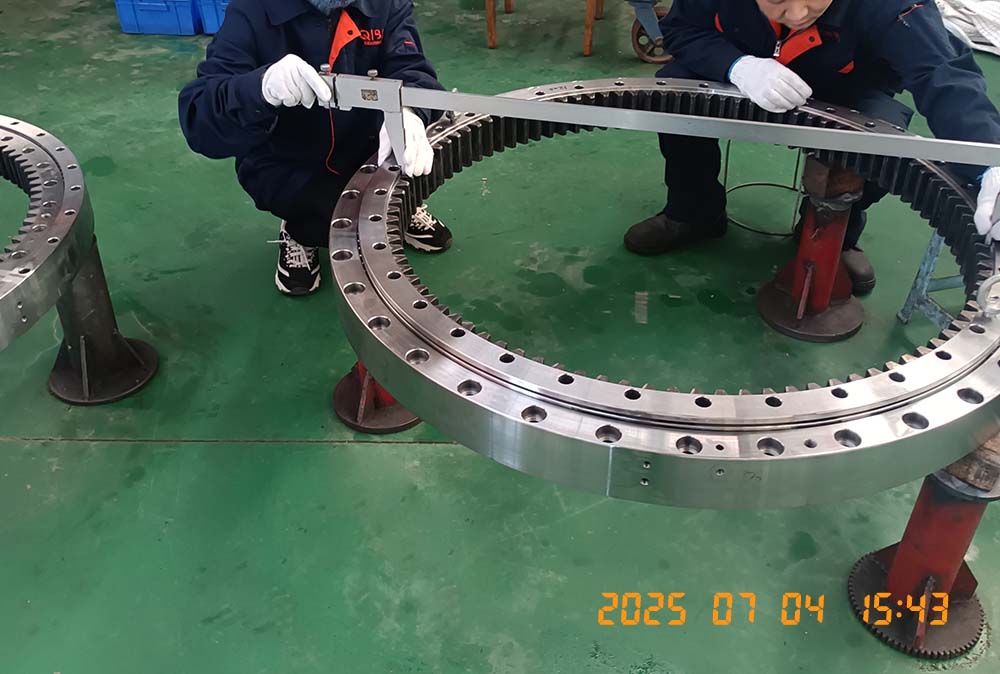
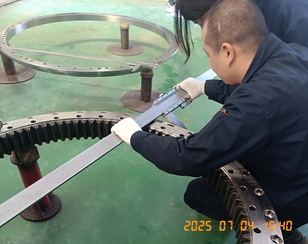
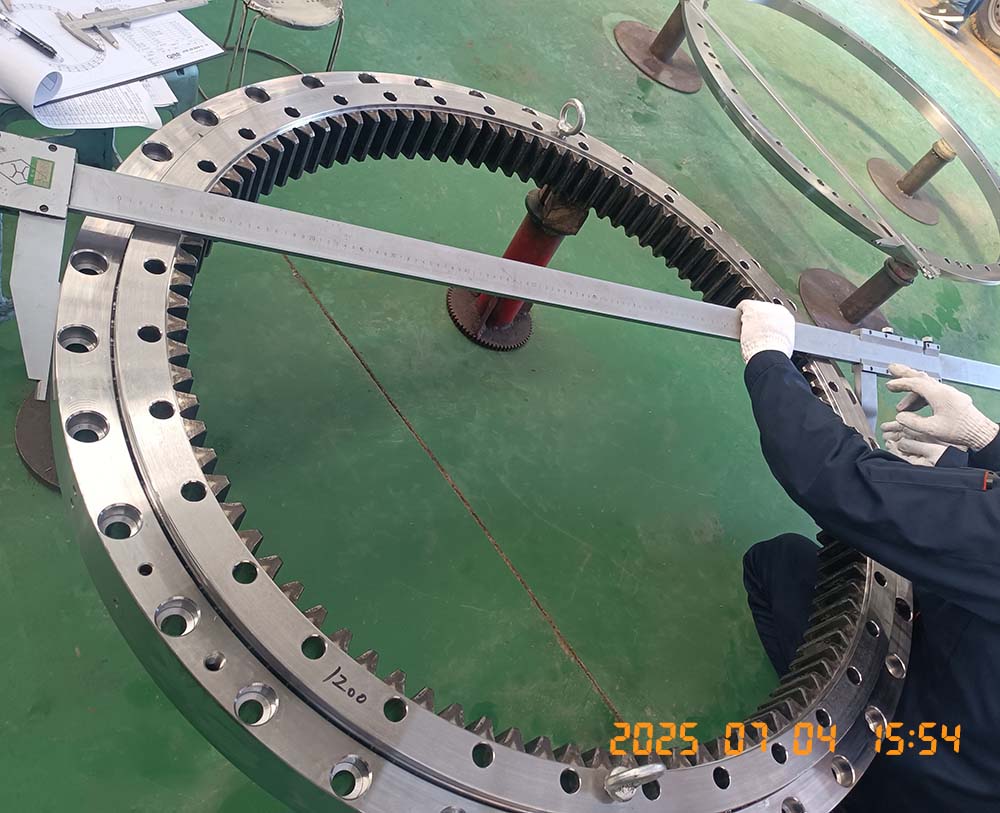
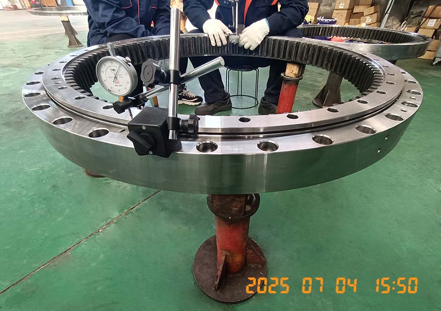
Dimensional Inspection: Comprehensive checks using Coordinate Measuring Machines (CMMs), laser scanners, precision gauges, and optical comparators to verify all critical dimensions, geometric tolerances, and surface finishes against the drawing. Gear profile and lead checks are performed if applicable.
Hardness Testing: Verifies surface and core hardness meets specifications at multiple locations (Rockwell or Brinell scales).
6. Surface Treatment & Corrosion Protection:
Cleaning: Thorough degreasing and cleaning to remove all machining fluids, swarf, and contaminants is essential before any coating.
Options:
Phosphating (Zinc or Manganese): Creates a crystalline conversion coating that improves corrosion resistance and provides an excellent key for paint.
Electroplating: Zinc or Cadmium plating for enhanced corrosion protection (environmental regulations often restrict Cd).
Painting: Application of primer and industrial-grade topcoats (epoxy, polyurethane) to external surfaces. Color coding for lubrication points is common.
Internal Protection: Raceways are typically filled with grease during assembly, providing internal corrosion protection. Special rust inhibitors might be applied before greasing, especially for long storage or harsh environments.
Specialized Coatings: For extreme environments (offshore), more robust coatings like thermal spray (Zn/Al) or heavy-duty paint systems are used. Hard chrome plating on raceways is rare but possible for specific wear resistance needs.
7. Assembly:
Cleaning (Again): Final meticulous cleaning of all components immediately before assembly in a controlled environment (clean room practices are common).
Component Prep: Rolling elements (balls or rollers) and spacers/cages (if used) are cleaned and inspected. Seals (often multi-lip elastomer seals like HNBR or FKM) are prepared.
Mounting Rolling Elements: The inner or outer ring is positioned horizontally. Rolling elements are carefully inserted into the lower raceway groove manually or using fixtures. Spacers or cages are installed to maintain element separation if designed.
Seal Installation: Seals are pressed or snapped into their grooves on both sides of the bearing assembly.
Greasing: The bearing cavity is packed with the specified high-performance grease (lithium complex, polyurea common) through lubrication ports. Quantity and distribution are critical.
Final Closure: The mating ring is carefully lowered and aligned onto the assembly. Preload might be adjusted if designed.
Plugging & Protection: Lubrication ports are fitted with grease nipples (zerks) and protective caps. Any open holes receive plugs. Exposed surfaces might get a final protective coating touch-up. Shipping protection (caps, covers, VCI paper) is applied to critical surfaces.
8. Final Testing & Packaging:
Functional Checks: Rotation is tested manually to ensure smoothness and absence of binding. Seal integrity might be visually checked. Gear mesh (if applicable) is inspected.
Documentation: Comprehensive inspection reports, material certificates, heat treatment charts, NDT reports, and assembly records are compiled into a final Data Pack accompanying the bearing.
Packaging: Robust packaging using timber crates or heavy-duty cardboard/steel frames is used to protect the bearing during transit. Lifting points are clearly marked. Environmental protection (desiccant, VCI) is included for long shipments or storage.
Conclusion:
The production of a slewing bearing is a sophisticated symphony of metallurgy, precision machining, thermal processing, and meticulous quality assurance. Each stage, from selecting the right steel alloy to the final greasing and sealing, contributes directly to the bearing's load capacity, rotational accuracy, service life, and reliability. Manufacturers must balance advanced technology with skilled craftsmanship to produce these critical components that literally keep the heavy machinery of our world turning smoothly under the most demanding conditions. Understanding this intricate process underscores the engineering value embedded in every slewing ring.